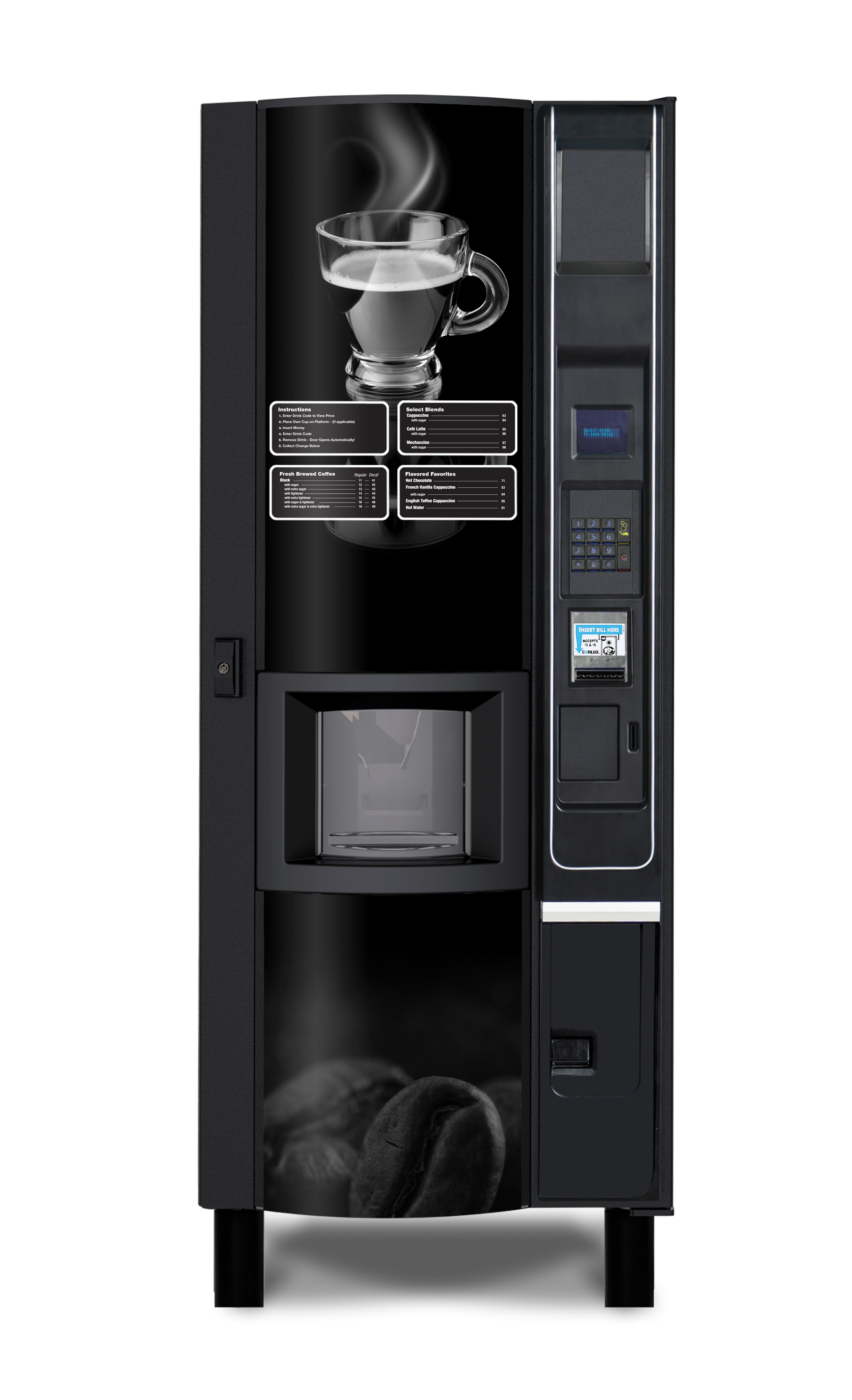
MarketOne Coffee Vending Machine
The MarketOne Hot Drinks Vending Machine for coffee, tea, and more features a European-design, state-of-the-art brewing system and filter system for precise ingredient controls to ensure a high-quality cup with superb taste, aroma, color and appearance is delivered each and every time.
Bring the European café experience to your customers with barista-quality hot beverages from the MarketOne Coffee hot beverage and coffee merchandiser.
Available in freeze-dried and fresh brew models, the MarketOne Coffee dispenses a broad menu of premium and specialty hot beverages, serving them just the way your customers like them. In fact, the MarketOne Coffee hot beverage and coffee merchandiser offers a comprehensive range of 11 core hot beverages with a total of 34 hot beverage combination options of coffee, specialty coffee, hot chocolate, tea, cappuccino and espresso.
Want to learn more?

White Glove Delivery

Financing Available
Made in USA

1-Year Parts Warranty

Lifetime Technical Support
The top-notch
vending experience
Features & Options
- ADA Compliant
- Greenlite Cashless Card Reader
- Fresh Brew
- Custom Graphics
- UVend Light Sanitization Technology
- Solid Shield Extended Warranty
++++++ 
ADA Compliant Customer interfaces and payment systems are at or below the 2021 ADA mandated side access height.
Greenlite Cashless Card Reader Greenlite is a turn-key cashless solution incorporating the latest in card and mobile payment systems.
Fresh Brew Dispenses a broad menu of premium and specialty hot beverages, serving them just the way your customers like them.
Solid Shield Extended Warranty Purchase additional protection for your vending equipment that goes beyond the scope of the standard Limited Parts warranty.
Custom Graphics Engage customers with a customized graphic design that is meaningful to their location and supports your brand.
UVend Light Sanitization Technology Makes the high-touch surfaces of vending machines safer by quickly killing or inactivating some of the most common viruses and bacteria.
Specifications
(International electrical specifications available)
Selections
11 Major Selections & up to 34 Beverage Combinations of Coffee, Specialty Coffees, Hot Chocolate, Tea, Cappuccino and Espresso
Capacity
Up to 400 - 7 oz (210 mL) squat cups; Up to 384 - 12 oz (355 mL) cupsAccommodates cups up to a lip diameter of 2.9-3.25” (73-82.5 mm)
Payment Systems
Premium Electronic Coin Acceptor; $1, $5, $10 & $20 Bill Acceptor (Set for $1 & $5)
Electrical Requirements
All industry-standard MDB compatible devices
Standard Features
115 VAC/60Hz., 9.5 AMPS
Data Communication
DEX/UCS, EVA-DTS compatible, USB Download
Water Requirements
15-116 psi (1-8 Bar)
Height
72"
Width
27.5"
Depth
28"
Shipping Weight
*361 lbs.*Varies with configuration and options.
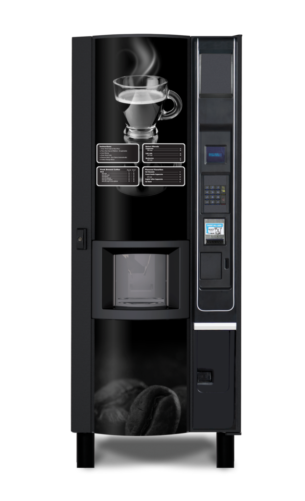
MarketOne Coffee Vending Machine
- Controls and Payment Systems at ADA Levels
- iVend Cup Sensor System
- 1 Year Limited Parts Warranty
- Manufactured in the USA
- Lifetime Toll-Free Technical Assistance
- Power Management Programming
- DEX Capable
- USB Software Upgrades and DEX Downloads
- LED Showcase Lighting
- Braille Identified Keypad
- Coin Mech and Bill Validators
- Extra Peripheral Opening and MDB Support
- Optional Features
- Greenlite Cashless Payment System
- Audio Interface for Sight Impaired Operators
- Freeze-Dried or Fresh Brew